Electrical Design |
Hardware Design Decisions
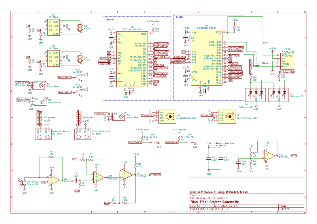
- H-Bridge Choice: The motor resistance was measured to guarantee with a worst-case 15V motor voltage the stall current would be below the TLE5206 H-bridge 5A limit. The H-bridge internal protection was sufficient and additional clamping diodes were not needed
- Wire: Stranded wires were chosen to increase circuit durability. 22 Gauge current rating was confirmed to surpass the highest predicted currents.
- Pull-Down Resistors. Pull-down resistors were added to to prevent leakage current from building a charge on the internal transistor gates and running the motor when the PICs were off
- Signal Processing Circuit:
- Trans-resistive Circuit: Resistors were tuned to provide a sufficient pulse amplitude about Vref, while not cutting the signal off during high ambient light conditions
- Hysteresis Stage: 3.3V was chosen as the pull up voltage to create a square wave that could be used with any PIC32 digital pin. The relationship between the two resistors connected to the comparator V+ was tuned to provide a hysteresis band that was not so narrow it would be triggered by noise but also not too wide such that it would miss the peak voltages
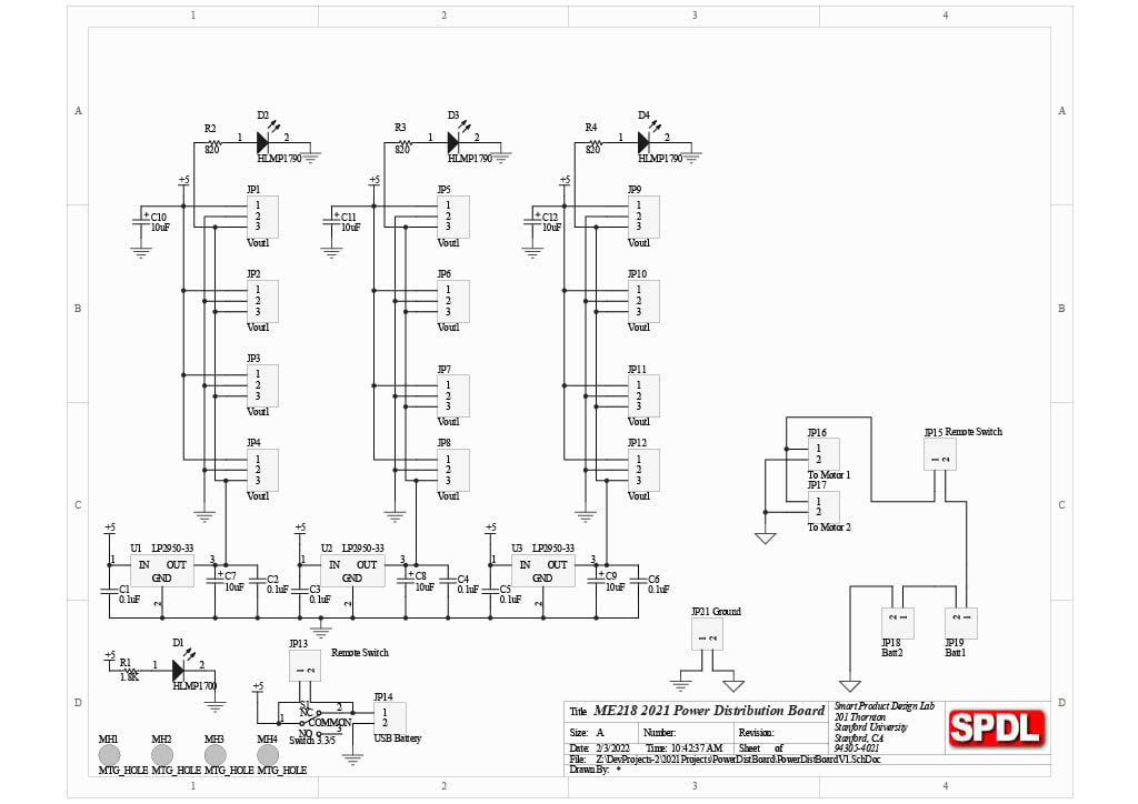
Power
The power distribution board was provided by the class instructors.
A 5A fuse was added in series with the JP15 remote switch to provide high current protection.
A 5A fuse was added in series with the JP15 remote switch to provide high current protection.
MPLabron Schematic
The MPLabron Schematic includes both PICs and all peripherals.
Power refers to the power distribution board outputs.
Power refers to the power distribution board outputs.